Front floor support removal and installation
After reviewing all the damage on the front end of the car and building a suitable jig to support it, it's time to start actually cutting metal off the car. This is collision damage I'm repairing here, so it's more complex than just stabilizing the car and swapping rusty old parts for new metal, which is already a pretty involved procedure.
All the frame pieces have to be replaced in a particular order, and my frame jig was built with this adjustability in mind. I need to be able to remove a part, and then place the new part correctly so it can be properly placed to support the new frame rail. Given my particular issues, the order for removing and replacing my frame parts is (1) Front right floor support, (2) Right side shock tower/frame rail assembly, (3) Radiator support.
In this post, I'm replacing the floor support, shown below. The rear of the floor support is still in the right place but the front is bent where it meets the frame rail that was shoved rearward. The new part has to be put back in the correct place which may not be the same place it was when it was removed. Without correcting for the displacement, I'd just be 'building in' the misalignment I was trying to correct.
 |
| Where the floor support lives on a 67 Mustang. No Torque Box in the way in 1967 for Fastbacks. |
 |
| Shiny new floor support, primed in SPI Black epoxy. |
While researching how to do this, I noticed that most folks who are replacing a floor support were also replacing the actual floor pan as well, seen here and here as examples (thanks to Alex and Mike). Typically the floor pan would get cut out first, and the exposed and easily accessible floor support is removed and replaced while it just hangs there in free space. I'm in the unusual spot of not having a rotted-out floor pan in my car, so I have no need to cut out and replace the floor. I like that the floor is original, plus I've already primed it. Seems like a shame to just cut it out and throw it away. That's fine, except I couldn't find any examples of anyone replacing the floor support with the floor in the way.
Not one to be deterred by a bad idea, I decided to try to replace the floor support while the floor is still in place. I think it worked out OK. I used sheet metal screws to hold these pieces in place while lining all the new metal up. Once I was happy with the placement and the measurements, I burned it in (shown in a later post).
A new floor support is about $30. I burned up a $5 spot weld removal bit as well. The overall removal and replacement took about 12 hours, including priming. But the research and planning took much longer. Hopefully someone can benefit from my work and save some time.
 |
| Critical floor support dimensions on the 67 Mustang frame drawing in the factory service manual. |
Blue shows known good measurements/dimensions on my car, Green shows which dimensions I'm using to line up the new part. Red is the bent part of the car, so the dimensions are not useable from there. Dashed lines are my derived measurements, solid lines are factory dimensions, highlighted in the blue boxes. Since the jig is level and the car is leveled to the jig, I simply have to get the height of the new floor support to match the other side. Remember, I need at least two measurements in each of the three axis of motion to make sure the new part is lined up correctly.

On convertibles in '67 and all later cars, there's a torque box in this spot to tie the floor support to the rocker panel. With no torque box in the way on my car (yet), I can use this measurement when replacing the new floor support. I also have the new torque box primed and on the shelf for installation later, so I also used it as part of the fit-up for the new floor support.
There are 52 spot welds holding the floor support to the car. I know this because I used the factory weld and sealant manual to figure out the location and quantity of spot welds that were holding all this together. If you're doing any type of metal replacement on a car like this, I cannot overstate how handy this is. I'm a big fan of RTFM [Reading The Factory Manual ;) ]. Most of the major parts houses carry these. I have the whole set. In this manual, Ford is telling you exactly how they put this car together. In almost every case, if this manual says there are 10 spot welds holding piece A to piece B, I found 10 spot welds, and placed more or less as per the manual. $20 to make my life easier? Take my money!
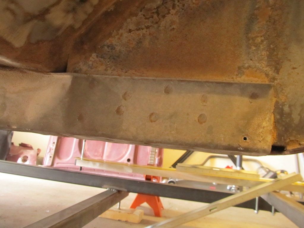
Spot welds that hold the floor support to the frame rail are visible here on the outside of the support.

More on the bottom. On the left of this image you can see all the wrinkling of the floor support from a 'minor fender' bender'.

There's also spot welds holding the floor support to the floor on all three sides.

And a couple holding the transmission tunnel support brace to the floor support, marked in yellow. These suck because they complicate the assembly sequence and there's very little clearance to get in between the jig and the floor support.

Can't tell by looking, but there's 10 more spot welds hiding on the inboard edge of the floor support as well.

Easier to see are the 16 spot welds holding the floor support to the floor.

Preparing to remove the spot welds with the Communist Freight $5 spot weld cutters.

For removing the spot welds on the bottom, I had a little clearance issue. I built the jig to match the factory datum line, which means there's only about 7 inches between the bottom of the floor support and the jig - too narrow for a standard drill with a spot welder removal bit. So, I picked up a cordless Milwaukee right angle drill like this one and it worked beautifully for this job.

Cutting welds out with wild abandon. Since I'm going to cut the frame rail out altogether later on, I didn't think I'd have to worry about stopping the cut on the first layer of metal. Then I realized it was a valuable practicing opportunity, so I starting cutting the rest out the right way by cutting one layer only.

Wish I'd thought of that before I started though...

Since I'm keeping the floor pan, I intentionally drilled all the way through the floor and floor support in order to create holes in the floor for my new support to weld to. When I install the new part later on, I should see new metal though all these holes. Then I'll weld the floor to the support from this side, which is way easier than if I'd tried to weld it from underneath.

Here's where the decision to keep the floor really sucks. The transmission tunnel brace is also welded to the floor support (per the weld manual). There are two welds on the bottom and four on the INSIDE of the floor support! So, to get to the welds so I could cut them out and preserve the transmission tunnel brace, I cut an access door on the side of the old floor support and then drilled out the welds. When installing the new part, I'll have to weld these to the new part by coming from above and welding the transmission tunnel brace tabs to the floor support. Again, that factory weld manual is pretty handy.

The last 2 welds are inside the floor support. Here's the outline for the access hole in the floor so I can cut the transmission tunnel brace welds from the floor support.

Zing! A new hold in the floor. You can't see the ground because what you're looking at is the inside of the floor support and the transmission tunnel brace. This hole actually has to be larger to get the welding gun in there later on.

Once all the welds are located and cut, the support came out pretty easily. I guess I could have just done the floor pan as well and saved some trouble, but part of the reason for doing just the floor support and keeping the floor pan is that I couldn't find anyone else who'd done it this way. Come to think of it, there may be a reason for this...


The new floor support all pre-drilled for plug welds to simulate spot welds (per the factory weld manual). Primer is stripped away from both sides where welding will be done so the welds won't get contaminated. These will be structural welds, so they need to be clean, hot an well-penetrated.

Comparing old support to new, a few things jump out. The old part is 16 gauge metal, whereas the new one is 14 gauge - much thicker. This will make welding a little trickier. Also, new piece is a little longer, so the hole in the bottom is in a different place relative to the rear of the part. Just keep this in mind when locating the new part relative to all those dimensions at the top of the post.

And since the frame rail here is bent due to the collision, I had to cut it completely out of the way so I could location the floor support properly. When it comes time to install the new shock tower/frame rail assembly, it should just slide right into the new floor support and be properly located.

Cut out the old part of the frame rail where it was welded to the floor support.

Blamo! After much measuring and checking, I installed the new floor support. It's held in with 'many' sheet metal screws to the floor plus the floor jack on the frame jig is applying a little upward tension.

Inside view, looking aft.The vertical gap between the transmission tunnel brace and the new floor support is too big here, but will get closed up better later on.

The view from inside. The sheet metal screws are installed facing up so now I have a bunch of sharp screws facing up hoping for some human flesh. Also notice the access hole I cut earlier has been opened up.
And the floor pan is still in place, which was the point of this exercise.
Comments
Post a Comment
Moderated and checked, albeit infrequently. Humans with real questions get answers, bots with spam get derezzed.