How to design and build a frame jig in only 6 months!
This one is long - but it's a big step, and one of the reasons for doing this blog is to show others doing this work how I did it.
Remember The Damage? It's time to start having hard conversations with ourselves. Specifically, how is someone (me) who has only done brake jobs, oil changes, and water pump replacements going to remove and replace an entire structural chunk of a classic American car without making a total shambles of it all? We're talking about pulling parts off the car that were really never supposed to come off - ever - and put them back exactly where they are supposed to be.
I need to put a new one of these on the car:

No worries, I have an actual Ford Shop manual for my car. There's whole paragraphs on how the power steering control valve works. There's gotta be pages on this. I'll just open it up the manual and see what it can tell me...

And, no kidding, this is all that's in the manual. One drawing. This, on its own, is not very helpful to me. Right off the bat I'm sure I don't know enough about this.
So after a LOT of research, reading, pondering, and sketching ideas on napkins, I finally feel comfortable enough to give this a go. All told, I thought about this part of the project for about a year as I was doing other stuff. Again, I'm slow, I know.
Here's the deal: in order to do this sort of work, one needs to build or acquire a body jig to hold and stabilize the car, then place the car on said jig so that the only parts that move are the parts that are being removed and replaced. The big questions here are:


I built the jig under the car to my specs and then lowered the car onto it. I used a laser level to make sure I get the jig's datum plane level.


Remember The Damage? It's time to start having hard conversations with ourselves. Specifically, how is someone (me) who has only done brake jobs, oil changes, and water pump replacements going to remove and replace an entire structural chunk of a classic American car without making a total shambles of it all? We're talking about pulling parts off the car that were really never supposed to come off - ever - and put them back exactly where they are supposed to be.
I need to put a new one of these on the car:

Dyncorn Shock tower/Frame Rail assembly from CJ Pony parts. Pretty!
No worries, I have an actual Ford Shop manual for my car. There's whole paragraphs on how the power steering control valve works. There's gotta be pages on this. I'll just open it up the manual and see what it can tell me...

And, no kidding, this is all that's in the manual. One drawing. This, on its own, is not very helpful to me. Right off the bat I'm sure I don't know enough about this.
So after a LOT of research, reading, pondering, and sketching ideas on napkins, I finally feel comfortable enough to give this a go. All told, I thought about this part of the project for about a year as I was doing other stuff. Again, I'm slow, I know.
Here's the deal: in order to do this sort of work, one needs to build or acquire a body jig to hold and stabilize the car, then place the car on said jig so that the only parts that move are the parts that are being removed and replaced. The big questions here are:
- what kind of jig? (body cart, fixed-base, or - my favorite - custom hack job)
- where to attach the jig to the car? (hint: not to parts that are going to be replaced)
- what should it be made of? (hint: not bricks or jack stands)
- what sort of music should one listen to while building a jig? (this one's a no-brainer: Will Smiths 1997 hit "Gettin' Jiggy With It" - lyrics [by Nas, who knew?] are interjected at appropriate points in the text.)
What is a body jig? Well, in short, it's a frame that supports the car while it's being worked on. It can be made of wood or metal, but it has to be sturdy enough to not deflect under the load of the car while parts are coming off and going back on. Basically, you're putting the car in traction. Note this is not the same as a rotisserie, which is great for general restoration work, but I wouldn't want to use one for structural work.
["Got to get jiggy with it..."]
Most of jigs I found online were for cars getting big pieces replaced due to rust damage. If you think about it, that's way better than collision damage - you just build the jig around the rusty, but un-bent car. Of course, it helps to have a frame shop confirm the frame is straight and true before you start, but in essence, that's it. But for collision damage like I have, I need to build the jig to support the car where the frame is undamaged or where it's the frame is supposed to be, This is harder for many reasons, one if which is that not-overly-helpful frame measurement drawing up above. I wish it had more, you know, measurements.
How many frame measurements do I really need? I gave this a lot of thought. My first guess was "a lot more than are on that drawing". But that's not very specific or helpful. It turns out, that's not even the right question to ask. What's really needed here is a way to ensure the new frame rail/shock tower assembly goes into place on the car correctly. The right way to look at this is to ask "Which dimensions do I have to control in order to make sure the new assembly is located correctly?" As it turns out, the correct answer is "at least 6".
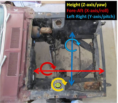
All these measurements really boil down to making sure the part in the right place relative to the rest of the car. So really, I just need to control:
- fore-aft position,
- the left-right position,
- the height off the datum plane
and the rotation around each of these three axis:
- roll,
- pitch, and
- yaw


If I can ensure I have enough measurement points to control these 6 axis, I can be sure I've put the new part in the right place. Each axis requires a minimum of 2 measurements, and some will do double-duty for another axis. So now I know what I'm hunting for: measurements that help me control these 6 axis. I spent a lot of time online trying to find other measurements to use in addition to the 9 or so the shop manual had for the front of the car. As it turns out, some of the numbers from the '69-'70 Mustang manual are also valid on the '67-68's, so between that and some other numbers I found from experts online, I was able to cobble together a list of about 15 measurements I felt good enough to work with. Drop me a line if you want the specifics. By request, I've included the frame measurements I used at the bottom of this post.
[..."I got the feeeeever for the flavor of a crowd-pleeeser...]
I decided to build a jig that will hold most of the car steady using hard mount points on the car and include some adjustability with strategically-placed scissor jacks to allow me to dial in the locations of the new parts. This is done so I can compensate for the old, bent parts coming off the car, and put new, unbent parts on the car in the correct place, and still be able to crawl all over the car and not worry about knocking it over (bad) or having it fall on me (worse).
Enough with the babbling. Let's build a jig.
The shop manual's frame drawing has a side view and a top view:

The side view has a line at the bottom called a 'baseline' - also called it a 'datum' line - and it's used as a reference. Essentially it's the zero line for height. The measurements on the side view are measured in inches up from that datum line. It could be anywhere actually, so you could move the datum line down a foot and just add 12 inches to each vertical measurement. I'm not going to complicate things (a first, I know), so my jig will use the datum as shown, which means I'll mount the car exactly as shown in the drawing - for example, the forward hole of the leaf springs at 7.98" over the datum line and the front bumper mounting holes are 12.94" over the datum line.
I chose to build mine out of 2"x2"x 0.125" square tube stock. It's easy to go all crazy here, some guys are using I-beams or 4-inch bars, some guys are using wood. That's cool, but I can't weld wood (yet), and if I can't weld my jig, well, what's the point? The math suggests the 2x2 square tubing is plenty strong enough for a nearly naked '67 Fastback, I just need to manage flexing of the jig over long runs. And in true beginner fashion, I'll weld the snot out of it, in keeping with the "overdoing it" methodology I've used thus far.
["...I makes it hot, gettin' jiggy with them...]
I made a ladder frame out of two 10-foot sections crossed by three 42" sections. I'm using leveling feet at the corners for leveling and regular bolts at the other intersections of the cross-pieces for extra flex prevention. The pieces are all clamped and leveled in the driveway as it's built so I don't accidentally weld in a flexed piece by mistake.
["...You tryin' to flex on me? Don't be silly, gettin' jiggy with it...]

Precision milk crates ensure the ladder frame is perpendicular in all the right places.

Leveling foot screws into grade 8 nut welded over a hole in the rail. This provides the fine adjustment for leveling the jig on the floor.

The datum plane is really just the imaginary horizontal plane formed by the tops of these long rails on the jig - that's my zero-level for all vertical measurements.

I built the jig under the car to my specs and then lowered the car onto it. I used a laser level to make sure I get the jig's datum plane level.

I borrowed Ted's Super Cool Laser Level. Includes plate for mounting on tripods or sharks.

I used sections of the bar stock as a poor man's retro-reflector (yeah, I went there) for leveling the jig. I marked where the laser should be on each bar, placed one in each corner, and then set the laser off to the side of the car to hit all four corners.

"No, Mr. Bond, I expect you to be level within 1/16 of an inch over 10 feet!"
Once the ladder frame was under the car, I built cross-pieces with vertical posts on them to attach to the car's hardpoints.

Crosspiece with vertical supports for the leaf spring mounting holes.

Crosspiece with vertical supports at Lower Control Arm (LCA) mounts.This one was assembled in place and then welded. I could get a grade 8 bolt through the driver's side LCA hole, but not the passenger side due to the bent frame rail.

Passenger side LCA Mount. These holes in the jig should be exactly centered in the LCA Mount. When the new piece goes on, they will be.

Scissor jacks (Communist Freight) and U-bolts. Holes drilled in base plate for U-bolts. This just happens to fit perfectly over the 2 inch bar stock I'm using.

Then the scissor jacks are mounted to the long rails and will be used to hold either the floor support (shown here) and a 2"x1" crossbar that the front frame rails will rest on. This it the adjustable part - since my frame is currently bent down and back, I'll use the jacks hold the old part for removal, and the raise the jacks to fine-tune to the height of the new assembly before screwing and welding it into place. The U-bolts can be loosened and the jack slid in and out of place as needed. Yeah, pretty frakin' awesome, right?

The front crossmember is welded directly to the jig to make it more stable. That whole front piece is also going to be replaced well, so I'm fine to weld directly to it.

Here's the jig supporting the front of the car. Three scissor jacks, two welded posts, and five bolted posts (there's one more at the idler arm mount). I left jack stands just under the rocker panels as 'just-in-case' backups if there was a problem, but they aren't actually touching the rocker. I'm also going to use the export brace and a Monte Carlo bar up top for locating these parts.

This pic is taken once the jig finally came out from under the car much later. In fact, this was the first time I'd seen it on its own since I built it under the car. I'm just showing it to give an idea of the overall design. The vertical posts are for the forward leaf spring mounts and the LCA mounts. The castors aren't on when the car is being worked on - instead, the leveling feet and bolts are used to support the whole thing,
Blamo. The Jig is up. The Car is mounted. The Parts are in. So let's get on with it.
["...Gettin' jiggy with it...<fade out>]
Details on Frame measurements used for the jig:
As mentioned above, I had to hunt and scrounge the web for measurements I could call 'real'. In the end I used the 67-68 frame drawing in the back of the manual (shown here), as well as some measurements from the 69-70 frame drawing. As it happens the front end between these two generations is pretty much the same, so a dimension on the 69-70 drawing will work on a 67 chassis. But I had to do a lot of research to figure out which would work.
Additionally, and you have to be careful here, some measurements come from real restorers posting measurements online taken off good cars. This is tricky because you have to know the source is really good enough to use - this is hard on the interweb.
So, here's what I used:
From the 67-68 Shop Manual Frame Drawing :

 [Update, 02/19/2016] - I forgot to mention two key pieces for this effort: the lower engine bay crossmember is a good reference point, as well as the export brace. I purchased a high quality aftermarket crossmember from Opentracker Racing because my factory-like repro fit so poorly in several areas. The new piece is designed to tie the frame rails together just behind the LCA mounts and it measures 29.5" bolt-to-bolt. This dimension doesn't appear on any frame drawing. The export brace is the "good" reproduction that is good for locating the tops of the shock towers to each other and the cowl.
One last piece of advice: measure it all one more time.
Good luck - hope this helps.
Details on Frame measurements used for the jig:
As mentioned above, I had to hunt and scrounge the web for measurements I could call 'real'. In the end I used the 67-68 frame drawing in the back of the manual (shown here), as well as some measurements from the 69-70 frame drawing. As it happens the front end between these two generations is pretty much the same, so a dimension on the 69-70 drawing will work on a 67 chassis. But I had to do a lot of research to figure out which would work.
Additionally, and you have to be careful here, some measurements come from real restorers posting measurements online taken off good cars. This is tricky because you have to know the source is really good enough to use - this is hard on the interweb.
So, here's what I used:
From the 67-68 Shop Manual Frame Drawing :
- Red boxes indicate actual frame dimensions used (6).
- Blue line indicates measurement between frame rails just above the forward edge of the floor supports (27.62", ±0.125", from here). The relative location is the blue dot on the side view.
- Yellow line indicates the measurement between the rear aprons at the top where the hood hinges bolt on (40.0", ±0.25, from same link as #2 - good thread, and Rusty428CJ is one of those trusted sources.)
- The green lines are the diagonals from rear floor support hole to front frame rail forward hole, projected down on a parallel plane (like all plan view dimensions). Basic geometry and the assumption that the angle drawn from between the two holes at the rear of the floor support (29.88") forms a right angle with the line that is measured (as in, not shown here) from rear hole to forward hole. These two diagonals need to match. With my bent frame rail, they didn't. Good dimension on my car (70.00") was measured at hole edges. Your mileage may vary.

From the 70 Shop Manual Frame Drawing :
- LCA mount, Left to Right (19.125")
- Forward frame hole, Left to Right (30.00")

One last piece of advice: measure it all one more time.
Good luck - hope this helps.
Comments
My advice is use the FSM drawings, and my end result as a guide on what a finished product could look like, but build one to spec for your car after you get it checked out on a frame machine. That will tell you if you need to make any other accommodations that the FSM and my dimensions wouldn't have told you.
Sorry, I don't mean to answer with a non-answer, but I think this is really, really application (read: car) specific.
-Emile
Emile
Many thanks for all your help and hard work
Not sure if my question is making it to you or not. Just wondering why you didn't use the rear most measurement on side view of the 67/68 dimensions? 15.57"?
I will take a chance on hoping you periodically check back. I am planning my attack , but don’t have much left under the floor pan. I am curious if the rockers, tops of front frame rails and bottoms of front floor extensions are all on parallel planes, if not, are any of the parallel? Are any parallel to the datum line?
Thanks
Bill
I went ahead and ordered front and rear framerails, and well as the floor supports. When I physically have those pieces to measure from, your 15 measurements will be more than enough to build a jig from with 8 reference points. The only thing I was really worried about the the space between rear frame rails and floor support extension. The shop drawing measurements all work out perfectly.
One other thing I did notice about the Liskey measurements is that it is based on a different datum. It has a 2 degree flatter rake. That's only about a 1/8" difference for the length of the car, but it adds up. It has measurements from several different holes than the shop drawing , which is weird. It makes it harder to check, too.
Anyway, thanks for putting this info out there, and I hope your project is going well.
Post a Comment
Moderated and checked, albeit infrequently. Humans with real questions get answers, bots with spam get derezzed.