Front Suspension Installation
Now that the rear suspension is place, I moved up to the front end of the car and started assembling all the running gear up there.
There's three major systems at the front of the car - suspension, steering, and brakes. I'm going to do the suspension first, which includes the wheel spindles, then the steering and the brakes. The factory assembly manuals don't really tell you what order things go in, and the factory service manual assumes each piece being installed is the only thing being worked on. This is fine in a shop environment, but maddeningly vague for me in my garage starting from a bare shell. As a result, I ended up removing and installing several pieces more than once. Lessons learned are at the end.
For the record, the suspension philosophy I'm employing here is "slightly upgraded stock". No rack-and-pinion steering, no coil-over springs, no tubular A-arms, or other such things. My goal is a car that retains the character and feeling of classic American iron. If I wanted modern or precise, I'd drive my Saturn (See how I did that? All of a sudden, the Plastic Fantastic is 'modern').


Lessons learned:
1. The sway bar end links should go on after the springs are installed.
2. Jack up the lower control arm to make the strut rod parallel to the ground so you can tighten the nuts on the front of the strut rods.
3. If the car isn't bent, note how much thread is showing on both ends of the front of the strut rod before removing it. Also note any shims on the upper control arms and the position of the lower control arm eccentric bolt before disassembly. All this feeds into alignment settings.
4. Castle nuts are to be torqued to LOWER SPEC numbers, then tightened to align the nut with the holes for the cotter pins. Don't tighten more than the lower spec. Yes, the FSM says this, but it's actually really worth reading and heeding.
5. The factory service manual has all the torque values in it. Stop asking Google and get the manual.
Astute readers will note the springs aren't in yet. That's a story in its own right. I'll save that for another day as they're more complicated than I expected them to be. Plus, any installation exercise that requires using an equation should get its own post.
Next up - steering!
There's three major systems at the front of the car - suspension, steering, and brakes. I'm going to do the suspension first, which includes the wheel spindles, then the steering and the brakes. The factory assembly manuals don't really tell you what order things go in, and the factory service manual assumes each piece being installed is the only thing being worked on. This is fine in a shop environment, but maddeningly vague for me in my garage starting from a bare shell. As a result, I ended up removing and installing several pieces more than once. Lessons learned are at the end.
For the record, the suspension philosophy I'm employing here is "slightly upgraded stock". No rack-and-pinion steering, no coil-over springs, no tubular A-arms, or other such things. My goal is a car that retains the character and feeling of classic American iron. If I wanted modern or precise, I'd drive my Saturn (See how I did that? All of a sudden, the Plastic Fantastic is 'modern').

Here's everything in the suspension system all laid out and ready to go on the car. There's some old part restoration and some new part unwrapping. New parts are the upper and lower control arms, roller spring perches, and stock big-block coil springs, all from Opentracker Racing Products. Fantastic stuff, great customer support, and quick shipping. The control arms are upgraded a bit, and the roller perches are known to be a significant upgrade over the stock rubber-based parts. All these parts feel like good stuff. Wheel spindles, strut rods, and sway bar + brackets are original parts off the car. The rest of the consumables came from NPD.

Part of the fun is the restoration of old parts. Here are the old strut rods. The threads on the front are still good, so we'll reuse them.

Here they are stripped clean and the old mounting bolts pressed out.

Strut rods (in black) and steering drag link (in cast iron) ready to go. That drag link is quite a story, I'll tell you about it next time.

Sway bar brackets getting cleaned up. Nothing's simple, though. I almost bought a new set plus polyurethane bushings for a few bucks until I realized these brackets are rare/special/expensive as they go with the 15/16" diameter sway bar on my car. They're special because they came on the few Mustangs that had the competition handling package suspension, as well as on all Shelby GT350's. So I decided to keep these, clean them up, and get proper bushings for them.

Here's the sway bar brackets cleaned and ready to get painted, along with the new bushings made by a small company called "Dead Nuts On". And they're spot-on replacements to the worn originals shown here.

I'm painting most of the parts that were originally made in cast-iron with a similar cast-iron look spray paint from Rustoleum. Similar in look and should keep the corrosion away.

Here's the cool 15/16" front sway bar that came off the car.
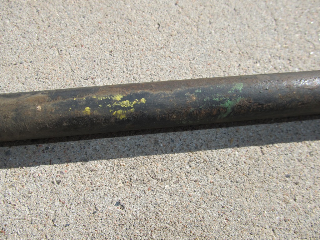
Like I've said, it pays to closely examine and clean these parts before stripping. Sure enough, hiding under the crud is the tell-tale yellow and green stripes that denote the competition handling package. I took pics and measurements for posterity's sake...

...and then stripped bare with the angry grinder and a wire wheel. There was enough surface rust to make this necessary.

I'm using a satin Rustoleum black paint for all the suspension parts, like the sway bar. I maybe should've used the epoxy primer, but this was a chance to try it out and see how it holds up. The crossmember, shown here before installation, came in a nice (powder?) coating - it's super nice, but apparently I'm not allowed to use the new kitchen oven for powder coating pats.

Fun fact - the 15/16" sway bar is contoured such that it actually uses the longer sway bar end link kit that comes on '68 and up cars (on the right), as the '67 parts (on the left) will be too short. Of course I discovered this after ordering my first set of parts...the catalogs won't tell you that little nugget!

Wheel spindles were blasted in Ted's blast cabinet and given the same cast iron paint treatment. The wheel spindle surface itself is left bare clean metal. That's where the inner and outer wheel bearings will ride, so no coatings are allowed there.

And now it's just a matter of putting it together. Upper arms and lower arms go in first, and then they're bolted to the spindle. Each of the arms already has a ball joint installed, so it's just a few bolts and castle nuts. The inner bolt on the lower control arm doesn't get torqued until the car is on ground on its own wheels.

Next up the strut rods and sway bar get bolted to the lower control arm and then to the chassis.

Repeat for the other side.

Here's the front of the strut rods. This setting is part of the wheel alignment adjustments. The factory assembly manual gives details on how much thread to leave exposed when installing new parts.

Sway bar mounted in it's new home.

And, because I can't help myself, I decided to restore the yellow and green stripes that were originally on the sway bar. I know, it's not a concours car, but I want assembly line identification stripes that no one will ever see back on my sway bar! My car, my rules.

Stripes marked off per the previous pics and measurements. In hindsight, I should've just used chalk to rough out the line and let it get as sloppy as the factory markings.

Cool, right?
1. The sway bar end links should go on after the springs are installed.
2. Jack up the lower control arm to make the strut rod parallel to the ground so you can tighten the nuts on the front of the strut rods.
3. If the car isn't bent, note how much thread is showing on both ends of the front of the strut rod before removing it. Also note any shims on the upper control arms and the position of the lower control arm eccentric bolt before disassembly. All this feeds into alignment settings.
4. Castle nuts are to be torqued to LOWER SPEC numbers, then tightened to align the nut with the holes for the cotter pins. Don't tighten more than the lower spec. Yes, the FSM says this, but it's actually really worth reading and heeding.
5. The factory service manual has all the torque values in it. Stop asking Google and get the manual.
Astute readers will note the springs aren't in yet. That's a story in its own right. I'll save that for another day as they're more complicated than I expected them to be. Plus, any installation exercise that requires using an equation should get its own post.
Next up - steering!
Comments
Post a Comment
Moderated and checked, albeit infrequently. Humans with real questions get answers, bots with spam get derezzed.